


Radial Internal Clearance Measuring
Of EXB Spherical Roller Bearings
The radial clearance of the bearing must be measured with feeler gauges over both rows of rollers before mounting and it must be recorded.
Pushing the bearing onto the tapered seat expands the innerring and reduces the radial internal clearance. The reduction in radial internal clearance serves as a measure of the interference fit, or where the radial internal clearance cannot be measured, the distance the bearing is pushed onto the seat can be used as a reference value.
The table below lists the values for spherical roller bearings of a shaft diameter range between 29 and 235 mm. The axial displacement values apply only to solid shafts made of steel/stainless steel and hollow shafts with bore diameters not exceeding half of the shaft outside diameter.


e = Radial internal clearance
During mounting the radial internal clearance or the axial displacement must be checked repeatedly until the proper radial internal clearance is obtained.
The minimum axial displacement applies to bearings whose radial internal clearance is in the lower half of the tolerance range before mounting; the maximum axial displacement applies to bearings of the upper half.

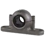
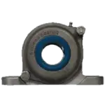
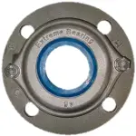
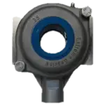
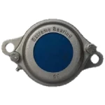
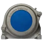
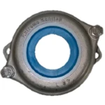
Bearing with adapter sleeve
Example
Mounting EXST050-AS-AS spherical roller bearing with standard CN clearance. Shaft diameter: 55 mm
Step 1
Measure unmounted radial internal clearance with feeler gauge. It should be 0,061–0,0813 mm (see table below).
Step 2
Position bearing on tapered seat until line to line is established.
Step 3
Using either a locknut, push bearing on the tapered seat until 0,0254–0,0305 mm removed.
Step 4
The final measured radial internal clearance should not be smaller than 0,0254 mm.
Clearance & axial displacement values
| Shaft Diameter d | Radial Internal Clearance Before Mounting | Reduction in Radial internal Clearance | Axial Displacement on Solid Steel Shaft | Smallest Radial Internal Clearance After Mounting | |||||||||||||
|---|---|---|---|---|---|---|---|---|---|---|---|---|---|---|---|---|---|
| (mm) | CN (normal) | Standard EXB C3 | Shaft | Sleeve | Shaft | Sleeve | CN | Standard EXB C3 | |||||||||
| Over | Incl | Min | Max | Min | Max | Min | Max | Min | Max | Min | Max | Min | Max | Min | Max | Min | Min |
| 29 | 30 | 0,0305 | 0,0457 | 0,0457 | 0,0559 | 0,0152 | 0,0203 | 0,3048 | 0,3556 | 0,3048 | 0,3048 | 0,0152 | 0,0203 | ||||
| 35 | 45 | 0,0356 | 0,0508 | 0,0508 | 0,066 | 0,0203 | 0,0254 | 0,3556 | 0,4064 | 0,3556 | 0,3556 | 0,0152 | 0,0203 | ||||
| 45 | 55 | 0,0457 | 0,061 | 0,061 | 0,0813 | 0,0254 | 0,0305 | 0,4064 | 0,4572 | 0,4572 | 0,4572 | 0,0152 | 0,0254 | ||||
| 55 | 65 | 0,0559 | 0,0762 | 0,0762 | 0,094 | 0,0305 | 0,0406 | 0,4572 | 0,6096 | 0,508 | 0,508 | 0,0203 | 0,0305 | ||||
| 75 | 90 | 0,0711 | 0,094 | 0,094 | 0,1194 | 0,0406 | 0,0508 | 0,6096 | 0,762 | 0,7112 | 0,7112 | 0,0254 | 0,0356 | ||||
| 90 | 110 | 0,0813 | 0,1092 | 0,1092 | 0,1397 | 0,0457 | 0,061 | 0,7112 | 0,889 | 0,762 | 0,762 | 0,0254 | 0,0406 | ||||
| 110 | 130 | 0,0991 | 0,1346 | 0,1346 | 0,1702 | 0,0508 | 0,0711 | 0,7112 | 1,0922 | 0,7874 | 0,7874 | 1,905 | 2,6924 | 2,0066 | 2,794 | 0,0508 | 0,066 |
| 130 | 150 | 0,1194 | 0,16 | 0,16 | 0,2007 | 0,066 | 0,0889 | 1,0922 | 1,397 | 1,1938 | 1,1938 | 2,6924 | 3,5052 | 2,794 | 3,6068 | 0,0559 | 0,0787 |
| 150 | 170 | 0,1295 | 0,1803 | 0,1803 | 0,2311 | 0,0762 | 0,0991 | 1,1938 | 1,6002 | 1,2954 | 1,2954 | 2,9972 | 3,9878 | 3,0988 | 4,191 | 0,0559 | 0,0889 |
| 170 | 190 | 0,1397 | 0,2007 | 0,2007 | 0,2591 | 0,0787 | 0,1092 | 1,2954 | 1,7018 | 1,397 | 1,397 | 3,2004 | 4,191 | 3,302 | 4,5974 | 0,061 | 0,0991 |
| 190 | 210 | 0,16 | 0,221 | 0,221 | 0,2896 | 0,0889 | 0,1295 | 1,397 | 2,0066 | 1,4986 | 1,4986 | 3,5052 | 4,4958 | 3,6068 | 5,0038 | 0,0711 | 0,0991 |
| 210 | 235 | 0,1803 | 0,2489 | 0,2489 | 0,32 | 0,0991 | 0,1397 | 1,6002 | 2,2098 | 1,7018 | 1,7018 | 3,9878 | 5,5118 | 4,191 | 5,6896 | 0,0787 | 0,1194 |